 |
ADI-1 Inside
Behind design, in front of technical issues and measurements The ADI-1 is a small but extraordinary 20 bit AD- and DA-Converter, well designed, representing the actual engineer's approach. In this Tech Infopaper you will find much information, normally not presented in general overviews or the manual. Analog to Digital The analog inputs use Neutrik's combi jack, thus providing
XLR- and 1/4" TRS jacks. The input stage is built in a servo
balanced design. When used unbalanced it automatically corrects the
gain by 6 dB. Thanks to this it doesn't matter how the inputs are connected,
the level is always as it should be. Changing the working level between
+4 dBu and -10 dBV is done with a special damping method already in this
stage. Although there is only limited supply voltage of +/-5 Volt available,
this technique allows a maximum input level of +20 dBu.
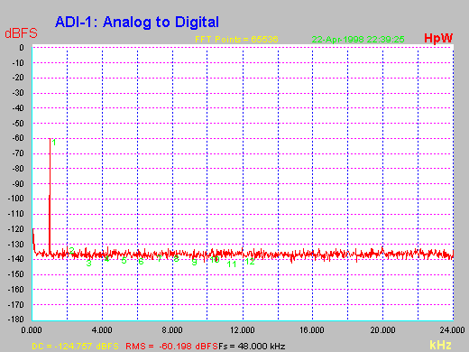
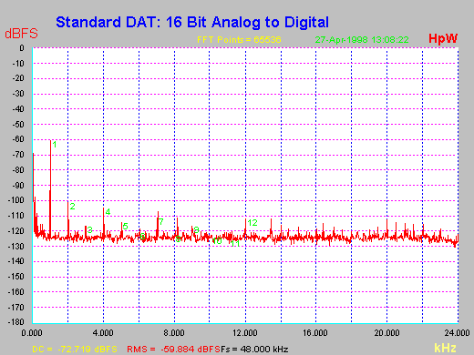
Just compare this to the measurement made at a normal consumer DAT. Because most users already own one these devices are often used as AD-Converters. In this case not only the balanced input and the professional input level adaption is missing. Of course a 16 bit converter won't reach the specs and quality of a 20 bit chip. So it's no wonder that the diagram shows distortion and a 12 dB higher noise floor! That's why many engineers claim the 20 bit chips to be perfect 16 bit converters.
The digital output stage is made out of a CS8402. The chip sends its digital signal to a coaxial (Cinch) and an optical (TOSLINK) output in SPDIF format. The so called 'Channel Status' is fixed to Consumer format without copy protection, so ADI-1 is compatible to most digital appliances. Even professional devices with AES/EBU inputs can often be connected to the ADI-1's output if a cable adapter is used. Controller The ADI-1 is very easy to operate thanks to a special programmed controller handling complex multiple processes inside the ADI-1. The integrated circuit (for insiders: a PLD) controls the sample frequency of the AD-Converter, the change to another sf, the display of the sf at the DA-Converter's input, the reset of the converter chips and their DC-adjustment, and much more. Most work has to be done when decoding the level information from the AD-Converters. Converting this data stream into a digital, 100% error free LED Peakmeter with reliable Over detection needs much resources. But it's the only way the ADI-1 will be usable without any further equipment, enabling you to make records with highest levels and lowest noise, without any clipping and distortion. DA Crystal's well known 8412 is used as digital receiver. A switch on the back of the ADI-1 decides whether the coaxial (Cinch) or optical (TOSLINK) input is active. As all Channel Status information is ignored, no copy protection, consumer/professional or even wrong information will prevent the ADI-1 from accepting the input signal. In other words: it works in every situation! The PLD decodes the already decoded information from the 8412 a second time, providing not only three LED's for the actual sample rate but also an error LED in case of a faulty or damaged signal. The output signal from the DA-Converter chip (AKM4320) is fed directly and unchanged into the servo balanced output stage. This stage is adjusted internally to work full symmetrical, and provides - like the input stage - an automatic gain correction of 6 dB when using balanced or unbalanced connectors. The used 4580 is not only low noise and low distortion, but also a very good line driver, so the analog output signal is available with low impedance and noise free at the XLR- and TRS jacks.
Perhaps you noticed that we claimed ADCs to be always
better than equivalent DACs. On the other hand our ADI-1 reaches 102 dBA
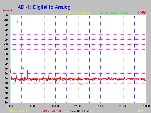
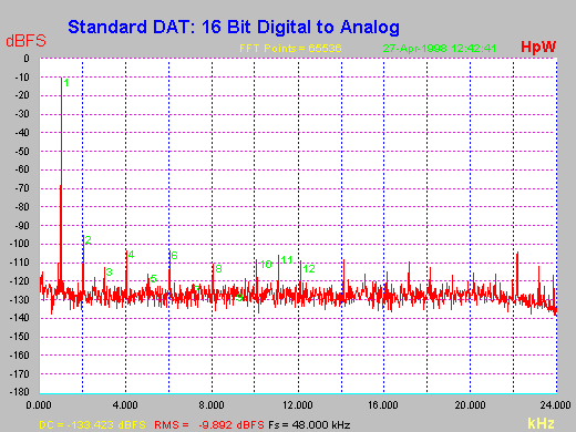
dynamic on AD, but tremendous 108 dBA on DA side. So the resolution of modern 20 bit converters is limited at low levels to 'real' 16 bit. Although the converters really have 20 bit resolution (can be proven with a hi-resolution FFT), all signals below the 16 bit dynamic range will vanish into the noise floor for the human ear. Therefore a 20 bit converter is a perfect 16 bit converter, but far away from its theoretical dynamic (120 dB.)
Power supply The design of the power supply has to be done
with regard to costs, mechanical issues and electrical basics. Because of
the size of the ADI-1 an internal transformer requires an expensive magnetic
shielding, or results in an unwanted hum. A design without an earth wire
(to avoid hum loops) would also be nearly impossible. An external power
supply needs no magnetic shielding, causes no hum inside the ADI-1 and is
much cheaper. As such an external transformer does not need an earth or
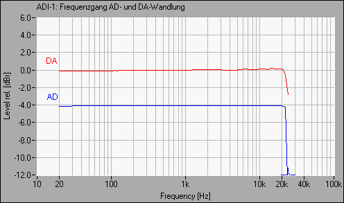
ground contact, there also will be no hum loop when using the ADI-1. Back to the power supply: we use a simple 12 V / 850 mA AC adapter. Inside the ADI-1 12 Volt AC is converted to positive and negative DC. There is one disadvantage of external AC adapters: the grounding design on the printed board is extremely delicate, that's why such devices often suffer from low but audible hum. The engineer has to design the layout very carefully (most times it needs several layouts to get the optimal result.) As the above FFT Analysis and the numerical values prove we succeeded in a total hum free design for the ADI-1. The small difference in the measurement values between RMS unweighted and A-weighted are caused only by the different noise sensitivity in the higher frequency range. Hum is not present, else we wouldn't have started the production of this device...
Notes on measurements RME does all measurements using professional audio analyzing tools and standardized methods of measurement. What's more the measurements are not done under strange or special conditions, but so as the device would be used in reality, thus not bothering you with values anyone can only dream of (and nobody knows where they come from.) Some companies reduced their efforts in examining their own devices to a reprint of the highest values published by the manufacturer's of the corresponding chips. These values can't be reached, because in the final device there is always additional electronics around the chip. And it is no secret that the values published in the chip's data sheet are often goals the manufacturer's want to reach (often only reached in later chip revisions or never.) At RME you don't need to read tests of independent magazines. We offer real and true measurements at no extra cost! Analog and digital measurements are made using Neutrik's A2D with its Windows software AS04 (www.neutrik.com.) This 'Audio Test and Service System' is capable not only of RMS unweighted and weighted measurements, like level, noise, distortion, or the above frequency response. Thanks to its easy to understand and fast user interface, the highly precise measurement results and its flexible input and output interface the AD2 is a must for every hardware developer. When working in the digital domain we also use a tremendous Windows software: HpW Works is a FFT analyzer with incredible resolution and accuracy (see the above FFT diagrams.) The included software generator provides many different test signals in 64 bit accuracy. Both systems are reference at well known and respected magazines, like ELRAD or c't (www.heise.de/ct.)
Glossary
Copyright © Matthias Carstens, 1998. |
||||||||||||||||||||||||||||||||||||||||||||
Copyright © 2002 RME. All rights reserved.
RME is a registered trademark. |

