 |
Synchronization II (DIGI96 Series)
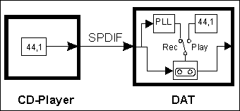
Sample rate, Word Clock, PLL and more: An overview for a better understanding With the continuing change from analog to digital technology a new part of digital audio confuses more and more users: the synchronization. But which kind of synchronization? In this overview we don't take a look on MIDI Time Clock or SMPTE, but on the problems that come up when connecting digital audio devices. CD to DAT CD-Player and DAT Recorder make up good examples and are suitable as help in understanding, as their principle of operation is easy to understand and well known to most users. In the analog domain one can connect any device to another device, a synchronization is not necessary. Digital audio is different. It uses a clock, the sample frequency. The signal can only be processed and transmitted, when all participated devices share the same clock. If not, the signal will have wrong samples, distortion, crackle sounds and drop outs. In practice digital appliances are master
or slave. The master is the clock reference, all slaves
follow the master. Each device which is able to receive digital audio signals is able to work as slave, else no error free recording would be possible. A DAT for example includes a special circuitry, that extracts the clock reference out of the digital datastream. A part of this circuit is the so called PLL (Phase Locked Loop.)
Master - or what? So each digital input can be used as reference clock
source. This feature is often restricted to internal usage. As digital devices
should also work without any input signal present they include an internal
fixed clock, a quarz
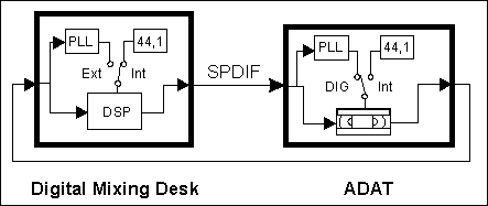
crystal. Because of this the DAT is working as master in playback mode. Confusing (and not yet covered through specific names) is the difference between a master and a 'complete' master. The 'complete' master is able to allow recordings without getting its clock out of the input signal, instead using its internal clock (this may be explained as master usage in Full Duplex mode.) When a digital device allows recordings without getting its clock out of the input signal there should be much disturbance, as there is no synchronization between the external and the internal clock. But if the combination and cabling of the used devices is done in a special way it is no problem. Digital Mixing Desk and ADAT Let's take a look at an example, where this kind of usage happens every day: a digital mixing desk connected to an ADAT recorder. The mixing desk is master, sends its data to the ADAT.
It doesn't matter if in playback, record or input monitor mode, the ADAT will always work with the clock received from the master (in this case the mixer), and send its data with the same clock back to the mixing desk. Such a behavior may be described as synchronizable. But this will make professionals think of timecode related control, for example to shuttle forward and backwards in sync to another tape machine. But what we are talking about here is not related to time domain or absolute position, it's just the synchronization to a sample clock with sample accuracy. To prevent disturbances due to misaligned sampling at the digital input of a mixing desk in master mode, the input signal has to be in total synchronicity to the signal send out from the desk. Note that in this case the inputs will not use the PLL to sync on the input signal, but are in sync with the internal clock of the desk. And that's exactly what's happening here: the desk sends out a digital signal controlled from its internal clock, the ADAT receives it, locks on it (using its PLL), sends out a digital signal with exactly this clock, which in turn could be received without any error from the digital mixing desk. More interesting is the other way round: the desk
works as slave and uses an external clock (the input signal), the ADAT is
master. The ADAT now uses the modes 'Int 44,1' or 'Int 48'. Compared to
a DAT the whole loop would crash when a recording is started. But the ADAT
is able to use the internal clock even in record mode, so everything works
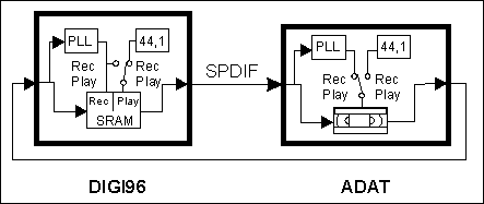
fine. DIGI96 Series The principle of operation of all DIGI96 cards can be seen in Fig. 3. All three versions are equipped with internal quarz clocks, enabling them to playback data in master mode at the fixed sample frequencies 32 kHz, 44,1 kHz, 48 kHz, 64 kHz, 88,2 kHz and 96 kHz, without any input signal needed.
This automatic behavior has many advantages, and additional allows true varispeed operation, because the card will follow every change in speed detected at the input. So all DIGI cards may work as master or slave, and can be synchronized from the input signal even in playback mode. As opposed to the DIGI32 series the DIGI96 series' memory is divided, and input (record) and output (playback) are no longer one circuit. Because of this the input circuit will always use its PLL to lock on the input signal, and the output circuit can be controlled by PLL or quarz. With this the DIGI96 series is enabled to behave like a 'complete' master device. Loop Mode Thanks to their 'complete' master technology the DIGI96 series is able to work in loop mode. The DIGI32 is not able to be used in loop mode without additional help. A typical application would be to use a digital effects device in loop cabling with the DIGI32. Digital effect devices in most cases operate exactly like the DIGI32, thus can be synchronized from their input signal, but won't use their own clock instead. Playing back audio data to the effects device and immediately returning the processed data back to the DIGI32 (which now records this signal) is therefore impossible. Despite Full Duplex this can't be done because both devices in the loop try to synchronize themselves on their input. When using a DIGI96 series card simply switch the card to 'Master' (setting 'Clock Mode') and everything works as expected. DIGI96/8 and ADAT The ADAT interface of the DIGI96/8 acts exactly like written before. Therefore a loop mode of ADAT and DIGI96/8 works without any problems as long as one of both devices is set to master mode. The other kind of Synchronization At last we again want to make clear that this Tech
Info only covers the sync needed and used between digital appliances to
send, receive and transmit digital audio data between them. There is another
kind of synchronization, providing an absolute time reference of the actual
position. For example when starting a PC based hard disk recording software
to play back not at the beginning of a track, but somewhere in the middle.
Then some kind of timecode is needed (MTC or SMPTE) and some kind of external
interface (like the ADAT BRC) that now controls the ADAT recorder(s) to
jump to this position, stop, enter playback and get close to the actual
position of the already playing PC software via varipitch (this is called
Chase Lock Sync.) This is not a question of word clock or Bitclock, but
again the Bitclock PLL will - because of the dramatic speed changes in Chase
Lock Sync mode - work much better than a simple word clock.
But even then the whole system does not act like a 'normal' tape recorder. For example the buffers in the software needed for record and playback result in a delay, that must be corrected by a manual applied offset to the software. In Chase Lock Sync mode another correction factor is needed, because the software calculates its absolute position based on ideal 44,1 kHz sample frequency, which of course is not given in reality.
Glossary
Copyright © RME®, Matthias Carstens, 1998. |
|||||||||||||||||||||||||||||||||||||||||||
Copyright © 2002 RME. All rights reserved.
RME is a registered trademark. |


