
This is the place for you to find more detailed technical information and special details about our products.
Additionally, you will find detailed explanations on various subjects, which didn't fit into the manuals.
TotalMix Part 1: The Hammerfall DSP Mixer - Hardware and Technology
The DSP in the FPGA
The Hammerfall DSP series includes several DSP functions - without having a DSP on board. Since our first card (the Digi24), RME goes for FPGAs (Field Programmable Gate Arrays.) Instead of working with hard-wired chips (like multimedia codecs), which offer functions implemented by the manufacturer, we use our own circuits, that are completely designed by us. This is possible with the FPGA, which is, in contrast to an ASIC (chip manufactured according to a customer's demands), even re-programmable. In the past, it was necessary to change an EPROM on our cards for this. The Hammerfall DSP's hardware configuration inside the FPGA can even be updated by a software / driver update.
FPGAs have become more powerful during the years. The newest generation used for the Hammerfall DSP (Xilinx Spartan 2) allows for computations in an FPGA (provided the designer is clever), that could only be performed by DSPs before. Even better: Again we have been able, thanks to optimal adaptions, to surpass the performance of pre-configured devices (Motorola, Sharc etc.) in the functions needed! Our mixer, for instance, processes up to 1456 channels internally with 100MHz and uses far more than 500MByte/s memory bandwidth - with this alone, a Motorola DSP is completely busy. Our FPGA on the other side, calculates the peak and RMS levels of 52 channels at the same time! Only as a side note, we may point towards the also included 3 ADAT receivers and transmitters and a completely digital SPDIF receiver and transmitter ...
In the following, the basic technology behind the Hammerfall DSP mixer is being described, including its realization in hardware with bits and bytes. Information regarding the software user interface, which presents all features easily overseeable and manageable, can be found in the Tech Info TotalMix: Software, features, operation.
What for ...
... do I need a mixer in an I/O-card? There are several scenarios:
- setting up delay-free submixes (headphone mixes)
- unlimited routing of inputs and outputs (free utilization, patchbay function)
- distributing signals to several outputs at a time
- simultaneous playback of different programs over only one stereo channel
- mixing of the input signal to the playback signal (complete ASIO Direct Monitoring)
The last point was most important for us at the beginning. Our present hardware (DIGI96 and Hammerfall series) were only working in replace mode because of the missing mixer, i. e. on the track just being routed input to output, you could only hear the input signal, but not the playback signal. This 'tape recorder mode' was a big step forward at the time, but it requires an additional external mixing console. With increasing computing power and improved software, more and more users want to use the 'mixer' provided with the software though. In order to hear the input signal together with the playback signal during monitoring, there are only two ways to achieve this: either the latency / buffer size of the card is so small (ideally under 6ms) that the software can completely calculate the data, or the card mixes input and playback signals on its own, so that monitoring can be latency-free (because the signal goes directly from input to output inside the hardware.)
In principle, a mixer being able to mix every input to any playback track once would have been sufficient - perfect ASIO 2.0 Direct Monitoring. After some thinking, however, this was way too little for us. If at all, it should be possible to mix any input channel into any number of playback channels - more flexibility has never been a drawback.
From this point, it was not far to the next demand: The playback tracks should be entirely mixable and routable in the mixer. This would allow for creating several completely independent submixes and freely routing the playback channels. Finally, when summing several tracks onto one, there will soon be too high a level: digital overload. Therefore, the levels of the physical outputs must be reducible. And because the playback tracks always pass the mixer, there must be a transparent 'unity gain' setting, guaranteeing bit-accurate playback. You can see already: even without effects and EQ, a mixer can become quite demanding ...
Internal
The essential criteria for the power of a digital mixer are the number of channels that must be processed simultaneously, and the internal resolution. Example Digiface: 26 inputs plus 26 playback tracks can be mixed to 28 physical outputs in any order. This means (26 + 26) x 28 = 1456 combinations simultaneously possible. The mixer must be able to calculate 1456 channels!
As long as monitoring would have been the only point for this concept, one would have got away with 16-Bit resolution. Including the playback tracks, this is no longer possible. Because they are always routed through the mixer, it does not only have to have higher resolution than 24-Bit in order to avoid rounding errors for gain changes, but it also has to supply additional headroom for gain rises and the summing of several channels.
Extremely high resolution does not make sense and causes a high consumption of resources within the FPGA. We have therefore decided to have a basic fixed-point arithmetic with the following values:
- The multiplier has 40 bit resolution. This comes from a maximum audio resolution of 24-Bit, that can be altered in gain with a resolution of 16-Bit (65563 steps) with a fader (24 + 16 = 40.)
- The adder has 36 bit resolution. From these, 7 bit are used for the necessary headroom (up to 52 channels with 6 dB gain can be mixed to one channel.) The audio signal has again 24-Bit resolution, the other 5 bit are used for the LSB to decrease rounding errors.
- The output signal is truncated to 24-Bit without dither.
- Faders: 16-Bit resolution, equals 65536 steps, which are provided following a special function for correct perception. Gain change input and playback channels: +6 dB down to maximum attenuation. Outputs: 0 dB down to maximum attenuation. Because of the screen display, the number of values that can be set with the mouse is dependant on the number of pixels. This is 137. In fine-mode (shift key), this value is multiplied by 8 for 1096 different gain values.
- Pan: pan law 6 dB. This means, the signal is attenuated by 6 dB in center setting. From center to left and right, there are 50 steps on either side. Linearly processed and displayed, from L 1.00 via 0.50 (C) to R 1.00.
Total Overload
As mentioned before, the mixer has two fundamental properties: It can not be overloaded and offers bit-accuracy at unity gain, i. e. it passes 24-Bit CRC tests.
In order to avoid internal overloads when summing (of 52 channels with +6 dB gain each in this case), the 24-Bit resolution of the input signals is not enough. Mixing of signals means adding, i. e. the new signal generally has a higher level than the single input signals. The worst case is completely correlated, in other words identical signals: already for two signals, the output level is twice as high (+6 dB.) With every further addition this factor is decreasing though.
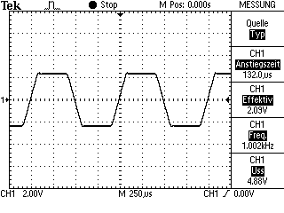
The overload safety of TotalMix can be demonstrated easily even without truck loads of external hardware. The following examples were made using the software HpW Works (to generate and analyze the test signal), a Digiface and a DIGI96/8. The oscilloscope used is a Tektronix TDS 210, connected to the analog output of the Digiface.
First, we digitally generated an interesting test signal (gotta have some fun ...), consisting of several sines with 0dBFS altogether, highest possible digital level in other words. In an application, the recorded signal was then sent to all 26 tracks of the Hammerfall DSP and still played back unaltered. The inputs and outputs of the Digiface used in this test were connected together, applying the played back signal also to all 26 inputs.
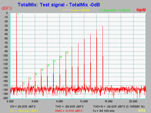
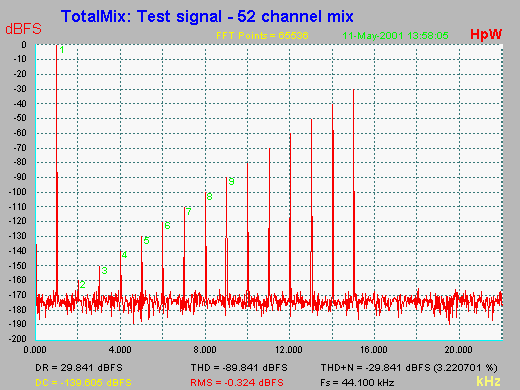
By means of TotalMix, all playback and input channels were now routed to the left channel of ADAT 1 (1+2.) This way, 52 channels sum up into one. For analysis, the output signal ADAT1 was routed through a DIGI96/8. As can be seen in this Screenshot, output channel 1 is of course totally overloaded, but after attenuation of the output level with the fader by ca. 40 dB, the signal presents itself unaltered.
This test is easy to follow up, but in fact not completely correct, because the signals at the inputs are delayed by two samples, which is the reason for the addition not being ideal. By the way, the addition of identical signals follows simple mathematical laws: log(10) of the number of channels, multiplied by 20 (same procedure as other dB-calculations in the audio field). This leads to some 34.3 dB, plus 6 dB max. gain, equals 40.3 dB. The overload headroom of TotalMix is 7 bit, translating to 7 x 6 dB = 42 dB, and is thus covering the theoretical maximum. In real life, the level rise is much less, because the added signals have less in common (correlation.)
Signal Quality
Besides, the signal quality is of course very important when making gain changes. The source signal should ideally not be changed, no matter how strong the level may be changed. This is only possible within limits though. For decreasing levels, the lowest components of the signal get lost automatically because of the limited resolution at the ports. In this case, we speak about 24-Bit, meaning levels below -144 dBFS.
As can be seen in the figure below, with 24-Bit it is well possible to create and display levels below -144 dBFS. The 2nd harmonic of the test signal e. g. is at -160 dBFS. By attenuation by 10 dB it can be shown without effort that TotalMix leaves the original signal unaltered (no visible distortions, no change of the level relations.) Even the 2nd harmonic shows cleanly at -170 dBFS.
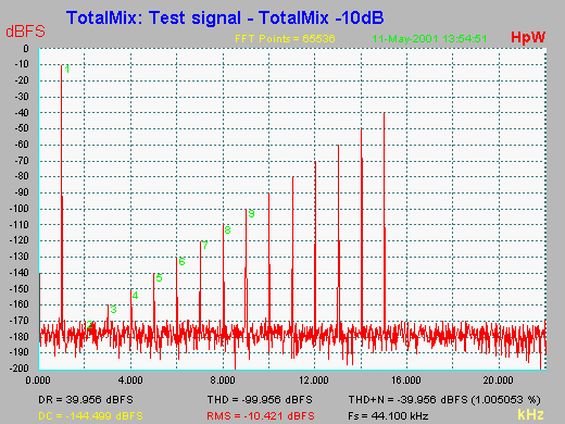
Attenuating by 30 dB lets the signal dive under the measurement limit of the FFT, i. e. the noisefloor. This noisefloor - in reality quantization distortions - is generated by truncation at 24-Bit, in this case caused by outputting the test signal via an ADAT port.
In conclusion, or 'Summing up', we can say: TotalMix causes practically no signal degradation thanks to simple fixed point arithmetic. Signal-to-noise ratio (SNR) and total harmonic distortion (THD) of the original signal are left practically unchanged.
But what happens, if the user does not see the overload display and the signal is clipped in spite of the headroom at the output? With a bad design, this may lead to calculation errors that can show as folding down of the original waveform in the anti-phase direction for the whole duration of the clipping. Even shortest impulses, which could be clipped inaudibly otherwise, cause dreadful and loud distortions.
Again TotalMix works exemplarily and limits the signal as clean as a precision brickwall limiter, without causing further disturbances. The left picture shows a full scale sine of several inputs mixed on one output. The right picture shows TotalMix limiting peaks in music, performing like a digital peak-clipper.
Software
All further functions necessary for easy and practical use are not determined by the hardware, but the software, which controls the hardware functions. This includes:
- storing of all settings
- special functions by hot keys: fader to 0, pairwise configuration, fine-mode etc.
- mute and solo functions
- different display modes
Glossary
16-Bit: 65,536 level steps or 96 dB theoretical dynamic range
24-Bit: 16,777,200 level steps or 144 dB theoretical dynamic range
ADAT optical: TOSLINK interface using the Alesis protocol. Allows for up to 8 channels at 24-Bit resolution and 48 kHz sample rate
Audio word length:: Resolution of the digital signal in bit
Bit: Smallest digital unit. With respect to resolution, 1 bit translates to 6 dB of dynamic range
dB: Decibel, logarithmic value for easier display of relations
dBFS: dB Full Scale. Logarithmic level value relative to digital maximum level
DR: Dynamic Range. Relation of maximum level to noise level with a stimulating signal at -60 dB
FFT Analysis: Fast Fourier Transform. Spectral decomposition of any given signal
LSB: Least Significant Bit
Sample rate: Number of samples / probes being taken of the audio signal within 1 second
SNR: Signal-to-noise ratio. Relation of maximum level and noise level.
THD Total Harmonic Distortion. sum of 2nd to 10th harmonic in relation to 1st harmonic.
Truncation: Cutting off the less significant bits of an audio signal.
Copyright © Matthias Carstens.
All entries in this Tech Infopaper have been thoroughly checked, however no guarantee for correctness can be given. RME cannot be held responsible for any misleading or incorrect information provided throughout this document. Lending or copying any part or the complete document or its contents is only possible with the written permission from RME.