|
|
| RMS/Peak Level Meter | Correlation Meter | Error and Level Analyzer | Channel Status Display |
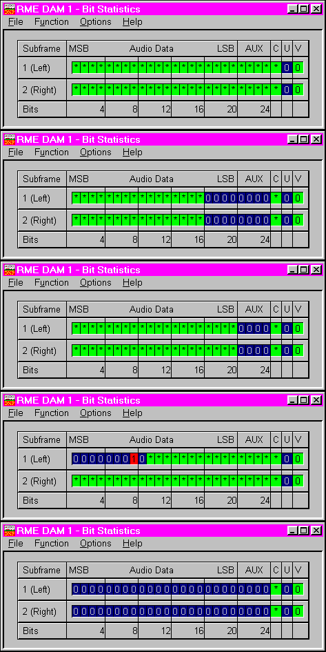
| Channel Status Modifier | Noise Level/DC Offset | Bit Statistics |
The complete un-installable Windows 95 / NT demo shows all features of version 2.0 Download Demo
You're already familiar to version 1.51? Then have a look to the new features of version 2.0.
| AUDIO LEVEL METERS (RMS Level Meter, Peak Level Meter, VU Meter) | |
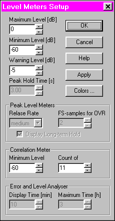
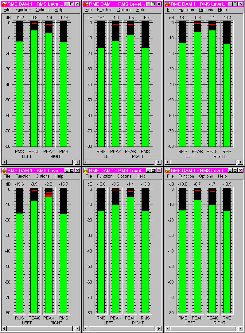 These
functions display the audio level as bar graphs and numerical values with a
resolution of 0.1 dB. Every single sample is used for computing Peak level
and RMS level. Overs are indicated when more than a user defined count (1 to
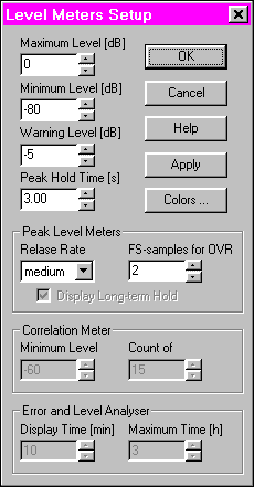
20) of consecutive full scale samples occur. The visible display range (maximum,
minimum and warning level) as well as the hold time of the Peak Hold function
(0.2 up to 100 s) can be set easily by the user. Full access to all
parameters allows to display the whole range or just to zoom in to a very small
range.
The level is measured in dBFS where a full scale (sine) signal represents 0dB. The RMS Level Meter uses 16 bits of the audio data stream, while the Peak Level Meter uses full 24 bit resolution, allowing the measuring of levels down to -160 dBFS. The Peak Level Meter also includes a long term peak hold display. The VU Meter is - thanks to a long attack time - ideal to display the loudness of a music related signal.
- Applications:
Level metering at recording and editing of audio material, i.e. at the output of ADC's, mixer consoles or effect processors; testing of audio equipment, i.e. signal to noise ratio, detection of level changes; monitoring of digital transmission lines.
| CHANNEL RELATIONSHIP (Correlation Meter) | |
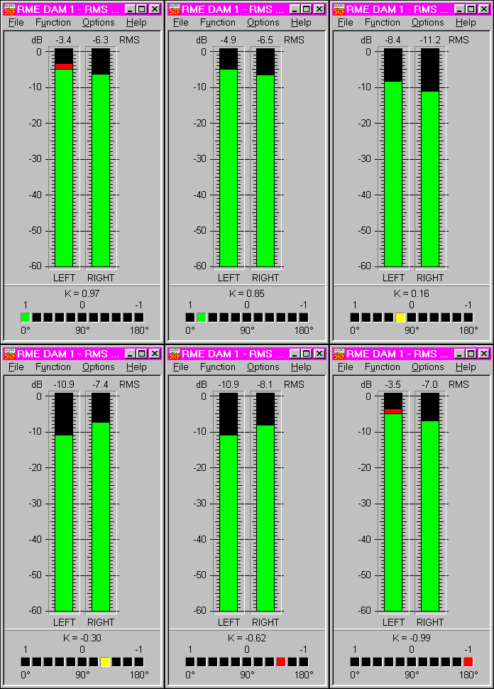
 This
meter consists of a RMS Level Meter and a meter for the mathematical correlation
between left and right channel (better known as phase), shown in numerical
values and a LED-scale. The values are computed using 16 bits of the audio
data stream. Below a user defined minimum level the display of the correlation
value is suppressed.
This
meter consists of a RMS Level Meter and a meter for the mathematical correlation
between left and right channel (better known as phase), shown in numerical
values and a LED-scale. The values are computed using 16 bits of the audio
data stream. Below a user defined minimum level the display of the correlation
value is suppressed.The number of LED's in the Correlation Meter is adjustable. If it exceeds 15 the width of each LED is reduced to the halve, so they need less space as shown in the picture to the right.
- Applications:
Checking the mono- and broadcasting compatibility; checking the microphone positioning for recording
| LEVEL AND ERROR LOGGING (Error and Level Analyser) | |


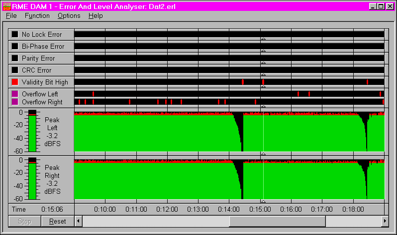
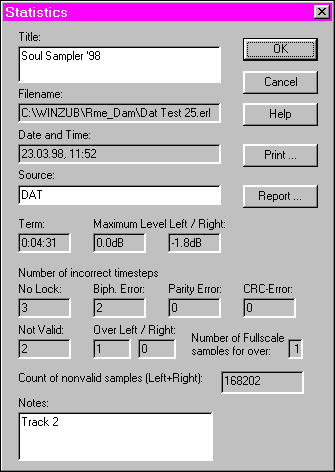 A
window called Statistics presents a complete summary of the recording, time
and date, maximum levels, the number of errors that occurred etc. The user
can complete these information by adding entries about the audio material
or other comments. A printout is also available.