 |
|

Word Clock Module for DIGI96® Series
Professional Word Clock Input and Output
-
Plus Masterclock and Test Generator!
|
|

|
 The
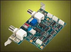
WCM MKII (Word Clock Module) adds a word clock input and output in
professional quality to the DIGI96 series cards. A low jitter optimized PLL
circuit, an integrated clock generator and a unique test mode extend the powerful
capabilities of our digital audio cards in a way many professional users have
asked for. The
WCM MKII (Word Clock Module) adds a word clock input and output in
professional quality to the DIGI96 series cards. A low jitter optimized PLL
circuit, an integrated clock generator and a unique test mode extend the powerful
capabilities of our digital audio cards in a way many professional users have
asked for.
Like with our other products we were not satisfied with the commonly used
standard circuits. Instead, thanks to a newly developed input stage, the WCM
gains unsurpassed compatibility and reliability. LEDs for power, test mode
and LOCK clearly tell what's going on. With this the WCM stands in the same
tradition as our other products: easy to use, always reliable, best performance!
The improved and enhanced new Word Clock
Module MKII offers additional modes, controlled by easy to operate
DIP-switches. With these modes the WCM is fully compatible to all currently
used word clocks. Input and output can be set to single or double speed
mode independently. An internal termination can also be activated.
Therefore T-connector and BNC-terminator are no longer necessary. The internal
clock generator can operate not only at 44.1 kHz, but also at 48 kHz. Thanks
to the single/double mode of the input those two sample rates extend to 44.1
kHz, 48 kHz, 88.2 kHz and 96 kHz internally.
|
|
|
 Thanks
to the intelligent co-operation of Word Clock Module and the DIGI96
series their combined usage is very easy. The activation is done by a
simple mouse click on 'Word Clock' in the area 'Clock Mode' of the settings
dialog. The area to the left, 'Output Status', allows to check whether the
word clock is used by the card or not. When a valid input signal is present
the third line changes from 'Clock Master' to 'Word Clock'. This display works
exactly like the green LOCK LED at the BNC input. Therefore you'll see directly
on the screen when a valid word clock signal is received and used by the WCM. Thanks
to the intelligent co-operation of Word Clock Module and the DIGI96
series their combined usage is very easy. The activation is done by a
simple mouse click on 'Word Clock' in the area 'Clock Mode' of the settings
dialog. The area to the left, 'Output Status', allows to check whether the
word clock is used by the card or not. When a valid input signal is present
the third line changes from 'Clock Master' to 'Word Clock'. This display works
exactly like the green LOCK LED at the BNC input. Therefore you'll see directly
on the screen when a valid word clock signal is received and used by the WCM.
The display of the sample frequency in the second line of 'Output Status'
does not represent the actual frequency in this mode, but the channel status
set in the digital audio signal. |
| |
|
|
| Module needs no driver and no slot on the
motherboard |
| Low jitter design: 2.5 ns typical in PLL
mode (44.1 kHz) |
| PLL works without dropouts even at more
than 40 ns jitter at input |
| High sensitive input stage works from 1
Vpp input level |
| Ignores DC offsets in the word clock net |
| Overvoltage protection at input and output |
| Short circuit protected output stage |
| Integrated clock generator, usable as master
clock or for test purposes |
| Internal clock switchable: 44.1 kHz, 48
kHz, 88.2 kHz and 96 kHz |
| Frequency range PLL input: 27 kHz - 102
kHz |
| Frequency range output: 27 kHz - 102 kHz |
| Input BNC, switchable high impedance (10
kOhm) or terminated (75 Ohm) |
| Output BNC, low impedance (10 Ohm) |
| Power supply: from DIGI96 board, 12 V DC,
45 mA |
| Standard slot, board dimensions 97 x 55
mm |
| 4 internal cables included |
|
|
|
- Test generator/Master clock
Pushing the switch 'Test Mode' forces the WCM to generate its own quarz
crystal controlled word clock, and to send it to all connected DIGIs. With
this the internal generator provides two functions: Test mode (the internal
word clock signal replaces the external at the BNC jack) and master clock.
The master clock allows to synchronize all internally connected DIGIs. As
the word clock signal of the test generator is available at the WCM's output
too, it can also be used as house clock, synchronizing the complete network
(studio.)
- Low Jitter Design
Devices using a common internal word clock PLL design often generate more
than 10 ns of jitter. The WCM's PLL is jitter optimized and reaches typical
2.5 ns at 44.1 kHz. This value is achieved although the WCM's PLL is located
on a separate board and stressed by electromagnetic fields inside the PC.
- Wide Range
The WCM is probably one of the first devices in the world that supports
the whole frequency range of 27 kHz to 102 kHz! With this you get the technology
of tomorrow today.
- Signal Adaptation Circuit
An ideal word clock signal is a 5 Vpp square wave. Usual word clock input
circuits are build with simple TTL receivers. Unfortunately often errors
appear, caused by wrong impedances (more than one termination resistor),
bad cables, connectivity problems or abnormal capacitive load, which lead
to a loss of level and signal deformation. Because of this the WCM was equipped
with a special AC coupled input circuit with 1 Vpp sensitivity, which can
use even a sine as input signal. While other devices often stop to work
at 3 Vpp or at slightly unformatted signals, the WCM stays locked. Thus
the reliability expected from a professional device can be guaranteed.
- Protection Circuits
To guarantee a long and successful operation the WCM's inputs and outputs
are protected against DC, overvoltage and shorts.
|
|
|
| |
Copyright © 2002 RME. All rights reserved.
RME is a registered trademark.
This website contains names and marks of other companies.
|
